一���、 General schematic of power quality solutions
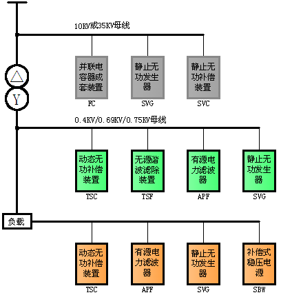
- compensation principle: overall planning, rational distribution, classification of compensation and balance on the spot;
In a variety of ways: can be divided into high compensation and low voltage centralized compensation and load compensation in three ways;
- mixed compensation: can be used SVG+FC, APF+TSC, APF+TSF, SVG+APF and other combinations of compensation.
二����、Introduction of harmonic control and reactive power compensation scheme
Introduction of high voltage compensation scheme
A rubber Limited by Share Ltd 35KV substation project
A scheme of automatic compensation and filter for high voltage reactive power
1. The general situation of the system
The main variable capacity of this period is 2 x 12500KVA, and the final stage is 2 x 12500KVA. Oil immersed three-phase load voltage transformer is selected. The main parameters of this period are as follows: voltage ratio: 35 + 3 x 2.5%/10KV impedance voltage: Uk=7.5% connection group: YNd11
2. Compensation equipment
L device name: high voltage reactive power automatic compensation and filter device
L model: W-TBB10-3750/417-AK
L Number: 2 sets (3750Kvar+3750Kvar)
3. The device consists of:
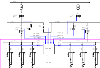
Reactive power automatic compensation device for automatic compensation device of cutting line, mainly composed of voltage and reactive power automatic control device, integrated protection device, vacuum contactor, voltage transformer, current transformer, series reactor, lightning arrester, grounding switch and shunt capacitor protection device composed of control etc..
4. Structure type
This device is a cabinet structure, reactive power automatic compensation is divided into 10kV 3750Kvar and 10kV II 1 bus bus 3750Kvar, according to the compensation principle diagram (Figure 1 and 2 female capacitor terminal cabinet, contact cabinet, wiring cabinet, PT cabinet for the original equipment), reactive power automatic compensation capacitor respectively by 3 cabinet for the first and second 10kV bus (3x1250 Kvar), 10kV I and II section of reactive power automatic compensation device consists of a set of voltage and reactive power automatic control, capacitor switching by vacuum contactor.
5, one connection scheme
W-SVG High voltage active dynamic reactive power compensation and filter device
1�����、conceptual design
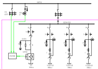
The transformer parameters of an enterprise: 1# variable capacity: 5000KVA; 2#, 3#, 4# variable capacity are 3000KVA; 5#, 6# are 1000KVA dynamic change, 10KV bus power supply. According to the actual situation of the field power consumption, we choose a dynamic reactive power compensation device plan, and install the high voltage dynamic reactive power compensation device (SVG) on the 10kV side of the transformer to realize the dynamic reactive power compensation. The whole set of equipment is used to improve the power factor of the system, improve the power quality, stabilize the power grid, save energy and reduce the cost and reduce the cost of operation.
Considering the various factors such as fundamental compensation and harmonic filtering, a set of fixed compensation devices (FC) is adopted, which are divided into three filter channels H5, H7 and H11. The installed capacity is 3000kvar. The high voltage dynamic reactive power compensation device (SVG) is designed with 3000kvar capacity.
2, SVG first wiring diagram
|
|
Fundamental
|
H3
|
H5
|
H7
|
H11
|
H13
|
THD %
|
|
harmonic current
|
1676 A
|
13 A
|
243 A
|
51 A
|
70 A
|
19 A
|
|
|
Harmonic voltage
|
395 V
|
0.8 %
|
2.3 %
|
0.9 %
|
1.5 %
|
0.5 %
|
3.64%
|
According to the above data, we will develop a variety of solutions for the selection of applications.
Scheme 1:TSF passive filter compensation scheme
Design 3, 4, 5, 7, 11 multiple frequency points filter branch, one connection scheme, such as the following figure:

The feature of the scheme:
- using LC passive filter circuit, 8 filter compensation branch is composed of multi frequency components.
The total capacity of compensation (output) - 700KVAr, installed capacity of 1575 KVAr, the target power factor 0.95.
- the Zhuzhou CSR thyristor module for electronic switch, no inrush current during switching, no voltage and no arc reignition.
- Effect Forecast: 5 times, 7 times, 11 times harmonic current absorption rate can reach more than 70%, into the point of common coupling harmonic current to meet the requirements of GB/T14549-93 standard. The power factor can be more than 0.95.
"The operation is stable and reliable, cost-effective.
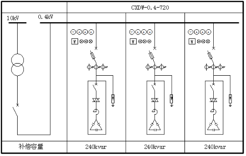
Scheme 2:TSC tunable dynamic compensation scheme
The first connection scheme is as follows:
The feature of the scheme:
In the method of capacitor and series reactor, the tuning frequency is lower than the minimum harmonic frequency generated in the network, so that the device is capacitive in power, improve the power factor is inductive in harmonic frequency, to prevent the harmonic amplification.
The total capacity of 720KVAr - compensation (effective output), installed capacity of 960 KVAr.
- the entire cabinet is composed of 8 pull type compensation module is assembled, with attractive technique, convenient maintenance and on-site capacity etc..
By Simon Kang - thyristor electronic switch module, dynamic load change.
Scheme 3:SVG (static var generator) +FC passive filter scheme
The compensation circuit is shown as shown in the following diagram.
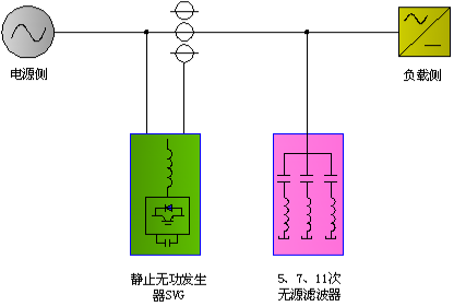
The feature of the scheme:
Hybrid compensation - by static var generator SVG and passive filter.
In the static var generator rated capacity is 350 KVAr, the passive filter compensation capacity of 350 KVAr.
- SVG has three operating modes: capacitive, inductive operation and no-load operation. It has the characteristics of continuous, rapid and dynamic compensation.
- 0 ~ 700kVAr can realize the stepless adjustment, the power factor is always maintained at 1.
In 5, 7 and 11 harmonic filtering rate > 70%.
Scheme 4:APF (active power filter) +TSC (dynamic reactive power compensation) compensation circuit wiring diagram:
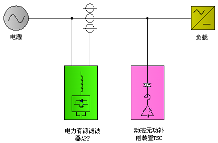
The feature of the scheme:
In the active power filter (APF) and dynamic reactive power compensation device (TSC) hybrid parallel compensation.
- APF bear the load harmonic current generated by the TSC bear compensation; reactive power compensation.
- TSC the total capacity of the reactive power compensation capacity of 300A 700kVAr, APF.
APF - a machine can compensate harmonic current, reactive power compensation of three-phase balance function, harmonic current compensation range of 2-50 times, the dynamic response time of 80uS.
- active and passive mixed use, play their respective characteristics and advantages. The design target of the total harmonic distortion rate (THD) is less than 5% and the power factor is more than 0.95.
三���、Comparison of the characteristics, functions and performance of the four schemes:
|
Function and performance characteristics
|
Active filter addition
dynamic compensation
|
SVG plus FC
|
Passive filtering facultative
Reactive power compensation
|
Dynamic reactive power compensation
|
|
Harmonic filtering function
|
Yes
|
Yes
|
Yes
|
No
|
|
Function of reactive power compensation
|
Yes
|
Yes
|
Yes
|
Yes
|
|
response speed
|
80μS
|
80μS
|
20mS
|
20mS
|
|
Harmonic elimination rate
|
>85%
|
Primary and secondary>70%
|
Primary and secondary>70%
|
——
|
|
Harmonic filtering times
|
2~50 second
|
5���、7�、11 second
|
5�、7、11 second
|
——
|
|
power factor
|
≥0.92
|
1.0
|
≥0.92
|
≥0.92
|
|
Harmonics
|
Standard
|
Standard
|
Standard
|
Fail to reach the standard
|
|
Protection function
|
Have
|
Have
|
Have
|
Have
|
|
Operation mode
|
Fully automatic
|
Fully automatic
|
Fully automatic
|
Fully automatic
|
|
Price comparison
|
high
|
high
|
Low
|
low
|
四���、Scheme Application:
Design drawings of a Research Institute:(TSC+APF)

Design drawings of the sinochemical science and Technology Research Institute: (local voltage compensation)

Anhui Textile Industry Design Institute:(TSC+APF)
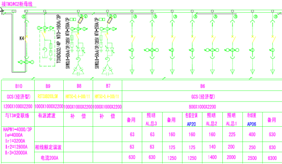
SVGTypical design diagram:


